Archive for January 11th, 2021
Stanadyne 4 Cylinder Injection Pump Cummins Diesel Engine DB4427-4954 (3919101)
Monday, January 11th, 2021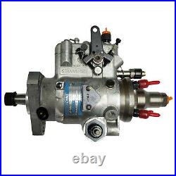
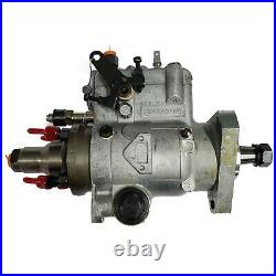
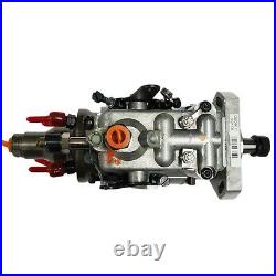
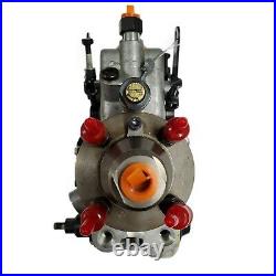
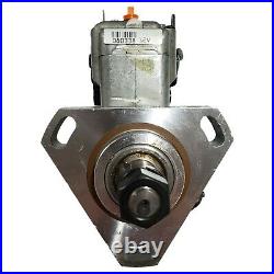
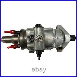
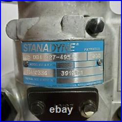
PLEASE MAKE SURE YOU MATCH THE SAME EXACT PART NUMBER BEFORE PURCHASING IT. LET US KNOW IF YOU HAVE ANY QUESTIONS. WE WILL TRY TO HELP YOU OUT. DESCRIPTION OF THE FUEL INJECTION PUMP. The injection pump is a single-cylinder, opposed-plunger, inlet-metering, distributor-type pump fitted with a mechanical flyweight-type governor and a hydraulically operated automatic advance mechanism. The pump is flange-mounted on the rear of the engine front mounting plate and is driven by the timing chain. A splined quill shaft, having a master spline at each end to ensure correct location, transmits the drive from the chain wheel to the injection pump drive hub. A central rotating member forms the pumping and distributing rotor, and this is driven by the drive hub through a splined drive shaft on which is mounted the governor flyweight assembly. Mounted on the outer end of the pumping and distributing rotor is a sliding-vane-type transfer pump. This pump raises the fuel pressure to an intermediate level, and as its capacity is many times the maximum requirements of the injection pump a regulating valve, housed in the pump end plate, allows excess fuel to be by-passed back to the suction side of the transfer pump. The pressure regulating valve, in addition to regulating the pressure of the fuel from the transfer pump, also provides a means of by-passing the transfer pump when priming the injection pump. 3, it will be seen that the valve is cylindrical and contains a small free piston, the travel of which is limited by two light springs. When priming the injection pump, fuel at lift pump pressure enters the central port in the regulating-valve sleeve and moves the free piston against the pressure of the piston retaining spring to uncover the priming port in the lower end of the valve sleeve. When the injection pump is in operation fuel at transfer pressure enters the lower end of the valve sleeve, forcing the free piston upwards against the regulating spring. As the engine speed increases, the transfer pressure rises, moving the piston against the pressure of the regulating spring to progressively uncover the regulating port in the valve sleeve and allow a metered flow of fuel to bypass back to the inlet side of the transfer pump. The transfer pressure, therefore, is controlled by a balance between the regulating spring pressure and the requirements of the injection pump at any moment. The pumping and distributing rotor revolves, and is a close fit, in the stationary hydraulic head. The pumping section of the rotor has a transverse bore containing twin opposed pumping plungers. These plungers are operated by means of a cam ring, carried in the pump housing, through rollers and shoes which slide in the rotor. The cam ring has four internal lobes operating in diagonally opposite pairs. The opposed plungers have no return springs but are moved outwards by fuel under pressure from the transfer pump, the flow of fuel and outward displacement of the plungers being determined by the setting of the metering valve and the speed at which the pump is rotating. As a result the rollers, which operate the plungers, do not follow the contour of the internal cam ring entirely, but will contact the cam lobes at points which will vary according to the amount of plunger displacement. The automatic light load advance mechanism operates by rotating the cam ring within the pump body. A ball-ended lever, screwed into the cam ring, is operated by a piston, one side of which is spring-loaded, sliding in a cylinder. The other side of the piston is subjected to fuel at transfer or drain pressure, according to engine load, which is admitted to the cylinder through the hollow locating bolt and a port in the cylinder wall. The pressure of fuel is controlled by the rotary and endwise movement of the metering valve. Machined in the surface of the metering valve is a helical groove. A vertical flat extends upwards from the helical groove and protrudes beyond the hydraulic head. Delivers consistent power output. Optional Built-in Advance and Timing Mechanisms. Speed and Light Load Advance. Cold-start and Warm-up Timing Advance. Adjustable Speed Regulation (3-5%). Low Speed Fuel Limiter. Locked Drive Shaft Timing. Fuel Curve Rate Shaping. Enables adjustment of the fuel curve between peak torque and rated speed. Makes the engine back up to peak torque RPM when a load is placed on the engine. Does not affect peak torque fuel. Eliminates need for separate lift pump. Insensitive to fuel quality and temperature variation. Ensures reliability in governing operation. Built for precision and robust operation. Available with 2, 3 or 4 plungers. Unique design reduces part count. Rotary design with porting bushing eliminates check valves. The item “Stanadyne 4 Cylinder Injection Pump Cummins Diesel Engine DB4427-4954 (3919101)” is in sale since Monday, March 23, 2020. This item is in the category “eBay Motors\Parts & Accessories\Car & Truck Parts\Air Intake & Fuel Delivery\Fuel Pumps”. The seller is “dieselrefresh” and is located in Rockville, Maryland. This item can be shipped worldwide.
- Modified Item: No
- Country/Region of Manufacture: United States
- Custom Bundle: No
- Interchange Part Number: DB4427-4954
- California Prop 65 Warning: This product can expose you to chemicals including Chromium (Hexavalent Compounds), which is known to the State of California to cause cancer, and birth defects or other reproductive harm. For more information, go to the California government website, you can search California P65 Warnings.
- Compatible Fuel: Diesel
- Manufacturer Part Number: DB4427-4954
- Fuel Pump Type: Mechanical
- Other Part Number: 3919101
- Brand: Stanadyne
- Fitment Type: Direct Replacement
- Warranty: 30 Day
- Mounting Hardware Included: No